

Measurement Techniques
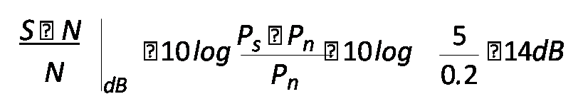
Signal to Noise Ratio
-
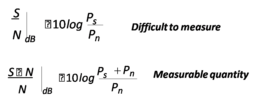
- A receiver produces a noise power of 200mW without signal, as signal is applied, the output level becomes 5W.
-
Noise Figure
- A figure of merit to measure the degradation of SNR of a system
-
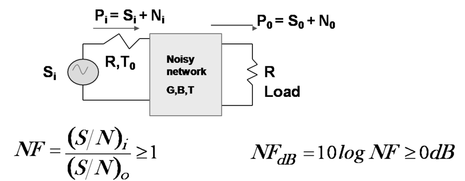
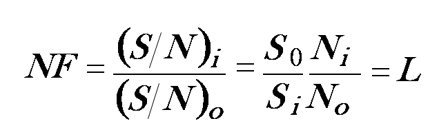
- For a passive device with G=1/L and in thermal equilibrium at the temperature T, N0 = kTB = Ni , So =GSi
-
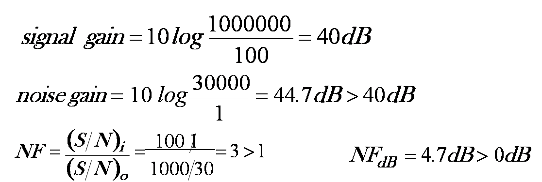
- An amplifier with input signal 100µW and the noise power is 1µW. The amplified signal is 1W with noise power 30mW.
-
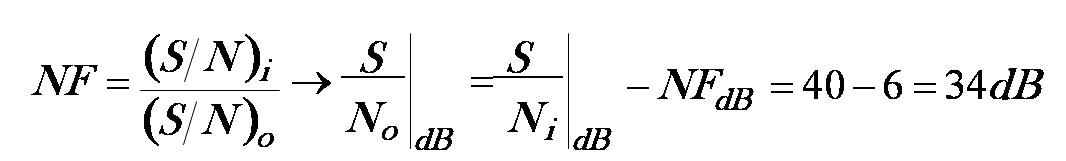
- An amplifier with NF 6dB has an input SNR=40dB
-
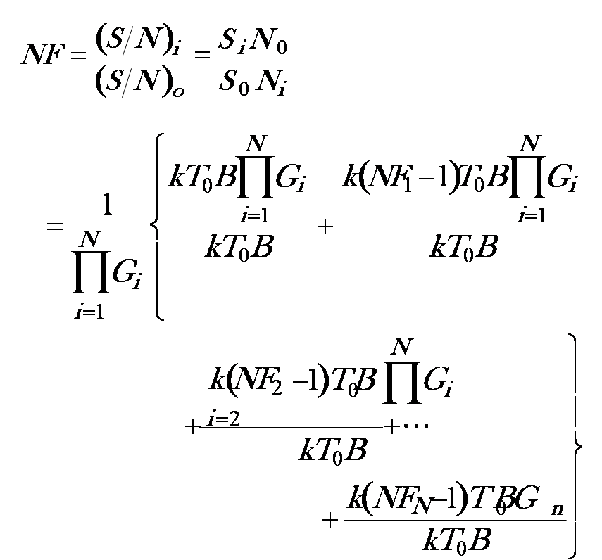
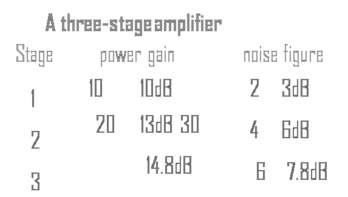
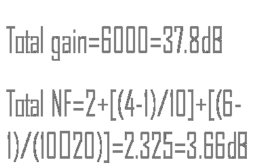
NF of a cascaded circuit

Frequency measurements
-
Two approaches: using frequency counter to measure frequency directly, and using probe to measure the wavelength in a transmission line.
Frequency counter approach
(1) Basic principle: direct counting <500MHz -
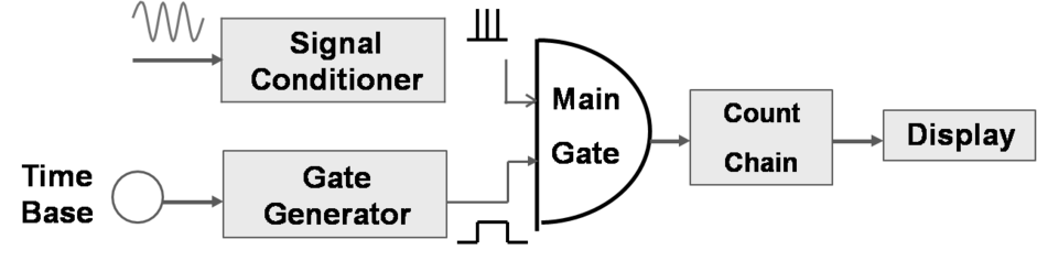
-
Using frequency down-conversion techniques for microwave signals
(2) Pre-scaling: divider circuit <2GHz
Transfer oscillator down-conversion: use PLL to relate the harmonic relationship between the low frequency oscillator and the input microwave signal > 40GHz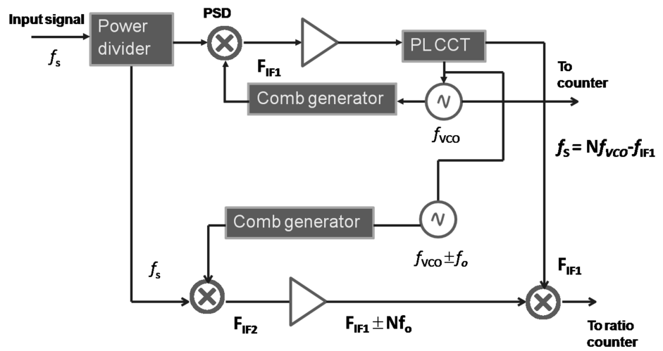
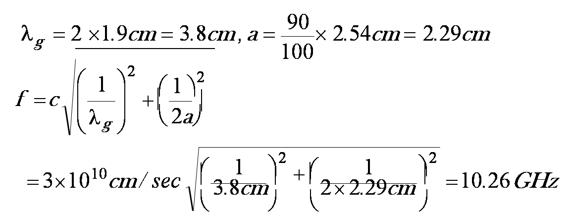
Wavelength measurement approach
-
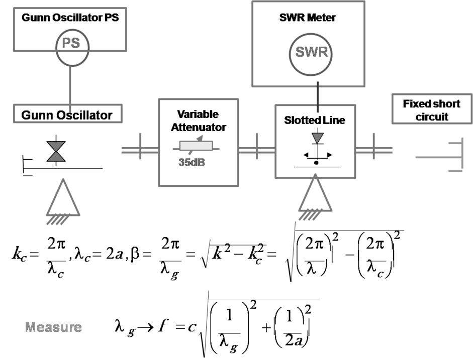
- Distance between two adjacent minima is 1.9cm in a WR-90 waveguide.
-
-
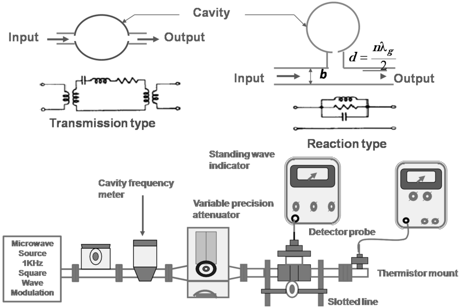
Wavemeter method
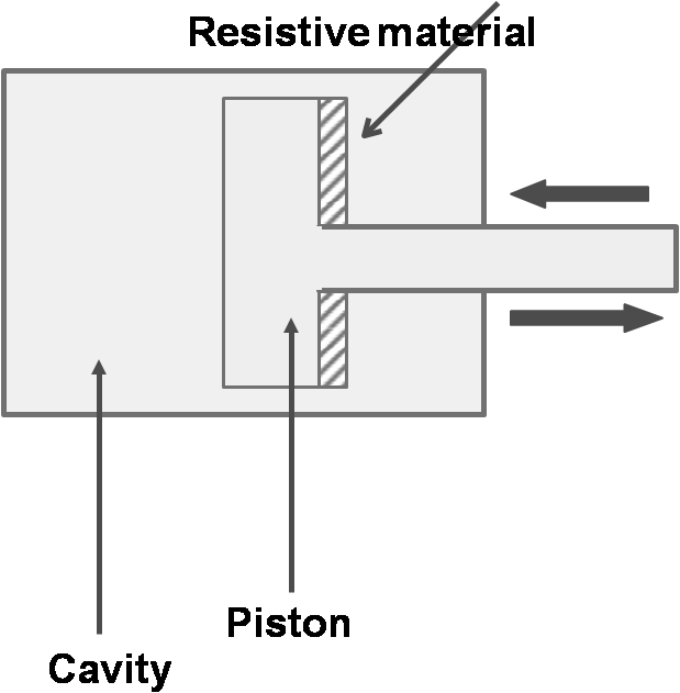
Operating principle
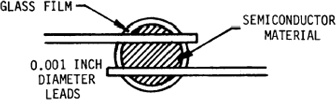
Detection devices
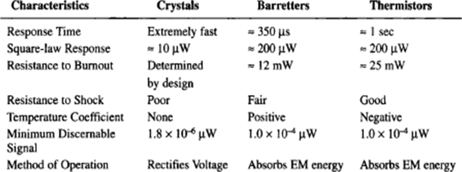
- Power detector: bolometer (thermistor and barretter), thermocouple voltage detector: crystal detector, Schottky barrier diode, GaAs barrier diode
-
- Thermistor: a metallic- component with a negative temperature oxide coefficient of resistance
-
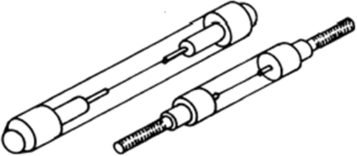
- Thermocouple: a pair of dissimilar metal (Sb-Bi) wires joined at one end (sensing end) and terminated at the other end (reference end). The difference in temperature produces a proportional voltage. Crystal detector: use the diode square-law to convert input microwave power to detector output voltage
-
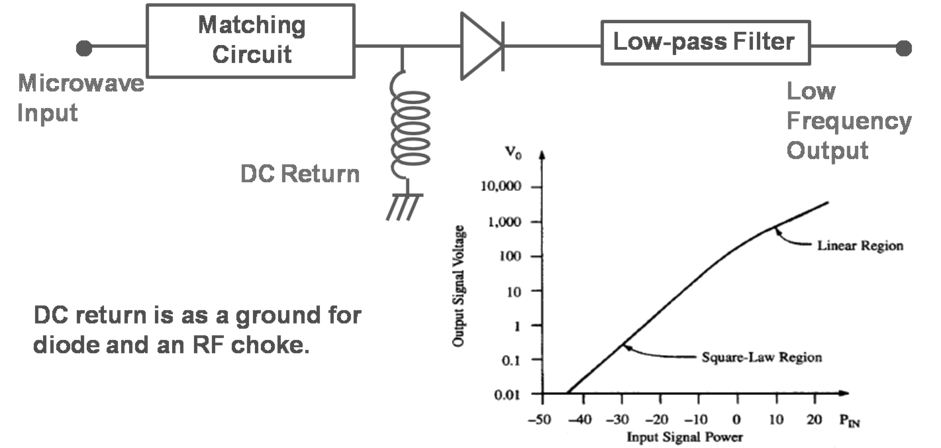
- Schottky barrier or GaAs barrier diode: high sensitivity noise equivalent power (NEP): the required input power to produce, in 1Hz bandwidth, an output SNR = 1 tangential sensitivity (TSS): the lowest detectable microwave signal power
-

-
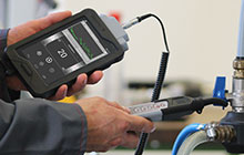
Power Measurements
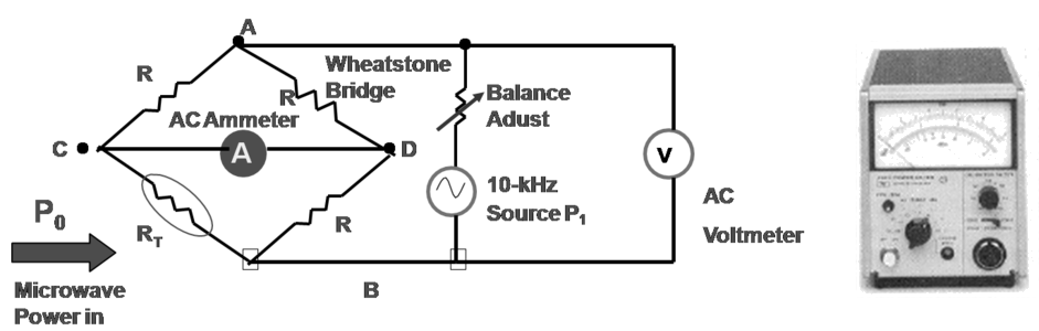
- Difficulty in measuring voltage or current at microwave frequencies → power measurement simpler and more precise Power range: low power <0dBm, medium power 0dBm~40dBm, high power >40dBm power detector sensitivity: diode ~-70dm, thermistor ~-20dBm Thermistor power meter
-
Power measurement arrangement
-
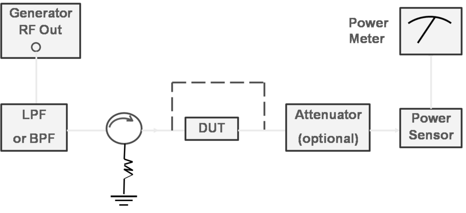
- Medium power case: use directional coupler or attenuator at the DUT (device under test) output
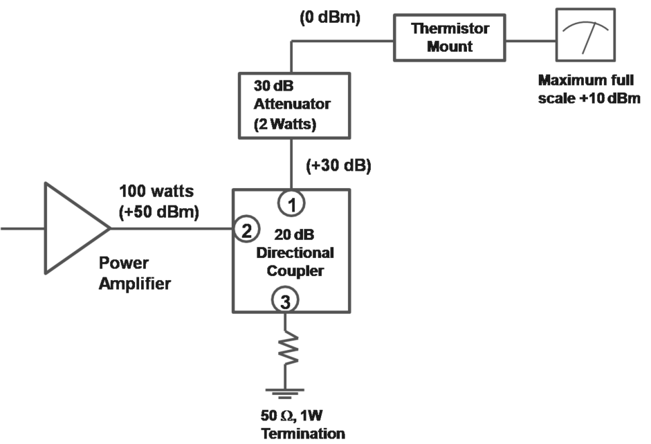
-
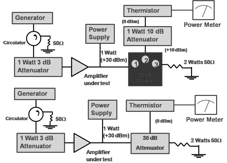
- High power case: use directional coupler in reverse direction Power Meter
-
Attenuation Measurements
-
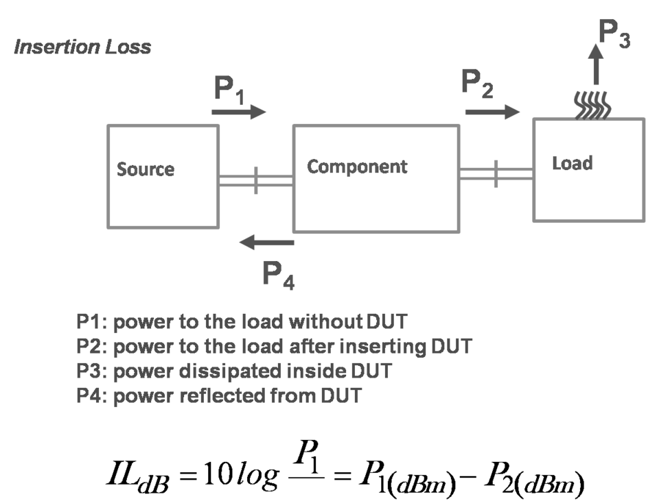
- If T: DUT reflection coefficient and T: DUT transmission coefficient,
-
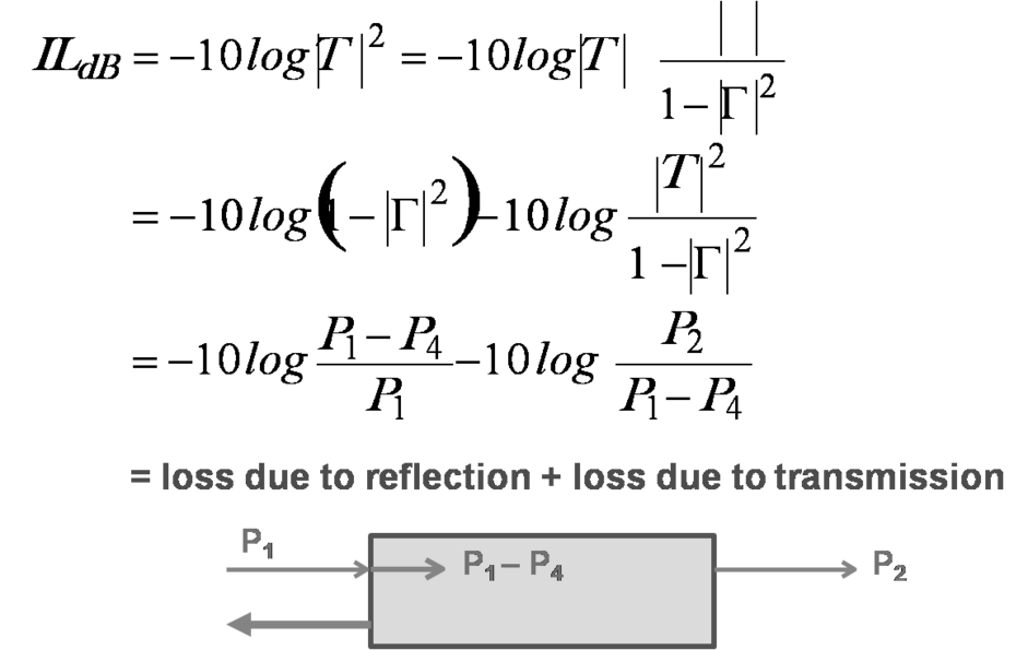
- P4 → Insertion loss is the characteristics of DUT itself. As input port and output ports are matched, IL= attenuation.
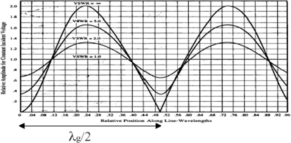
VSWR measurements
-
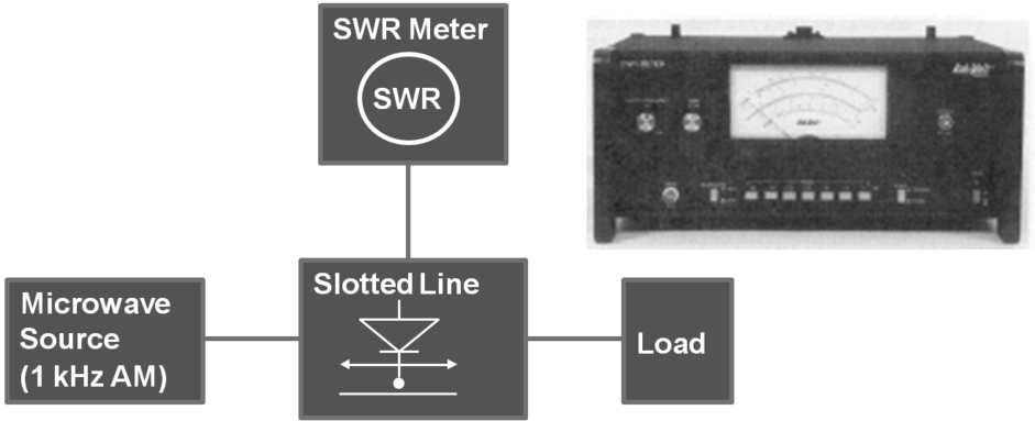
- If E probe penetrates too far into the slotted line, → disturb the field distribution and detected signal too strong to drive the detector out of its square-law region.
S- Parameters
- Problems to use Z- , Y- or H- parameters in microwave circuits
- ► Difficult in defining voltage and current for non-TEM lines
- ► No equipment available to measure voltage and current in complex value as oscilloscope
- ► Difficult to make open and short circuits over broadband
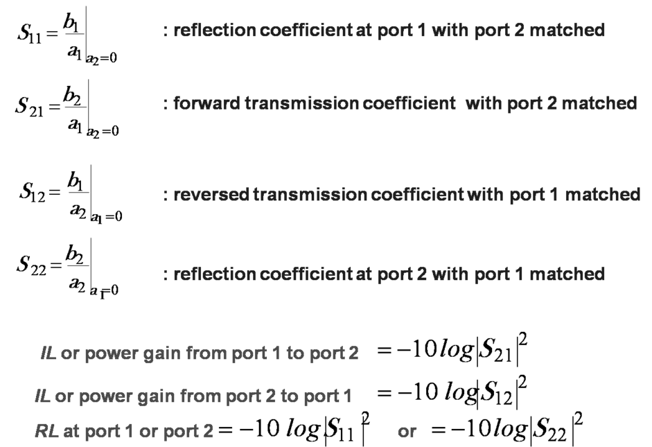
- ► Active devices not stable as terminated with open or short circuit. S-parameters of a two-port network
-
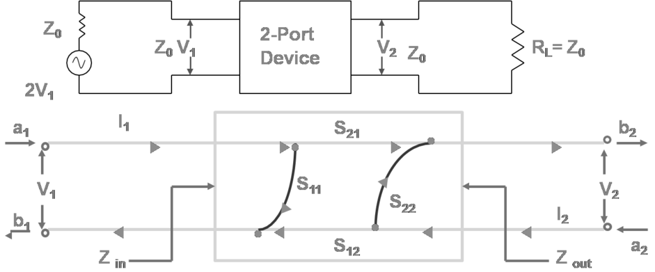
-
-
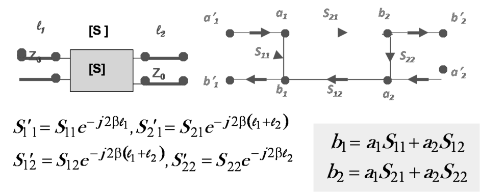
-
- Reasons to use S-matrix in microwave circuit
- ► matched load available in broadband application
- ► measurable quantity in terms of incident, reflected and transmitted waves
- ► termination with Z0 causes no oscillation
- ► convenient to use in the microwave network analysis
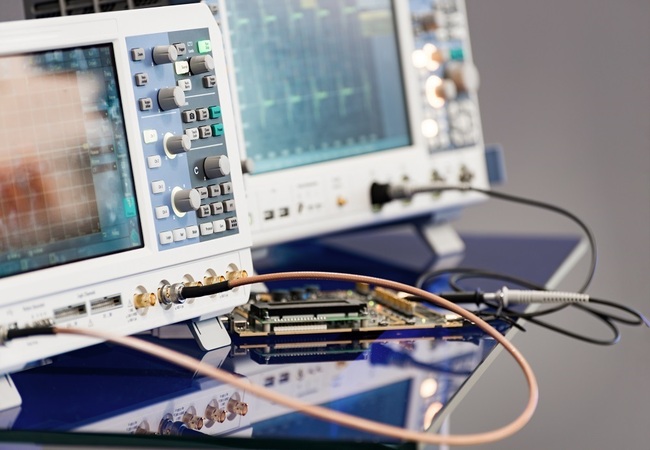
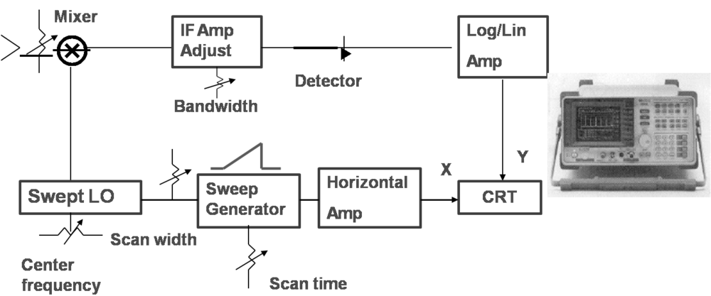
Microwave analyzers
- Spectrum analyzer
- Purpose: measure microwave signal spectrum, can also be used to measure frequency, rms voltage, power, distortion, noise power, amplitude modulation, frequency modulation, spectral purity,...
- Operating principle
-
Network analyzer
- Purpose: measure two-port S-parameter of a microwave device or network, can also be used to measure VSWR, return loss, group delay, input impedance, antenna pattern, dielectric constant,….
- Operating principle
-
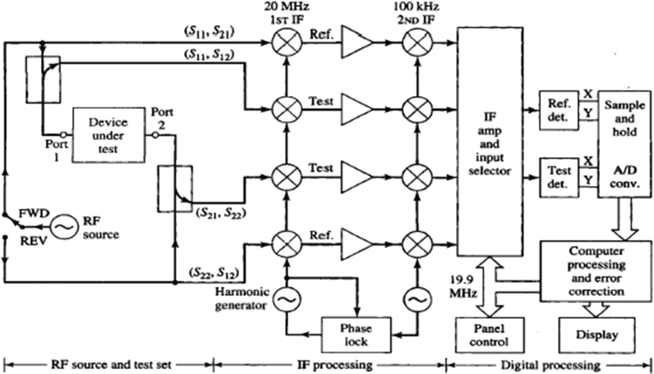
- Scalar network analayzers measures the magnitutude of S-parameters
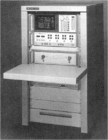
- Hp8510 vector network analyzer
-